 Account

Library of Failures
A library of classical material failure examples. Use the filter options to refine your search.
Torsional Overload of Lifting Chain
Fractured chain used in service to lift a skip used inside a grit-blasting chamber. The chain consisted of 10mm links with a C-hoo...
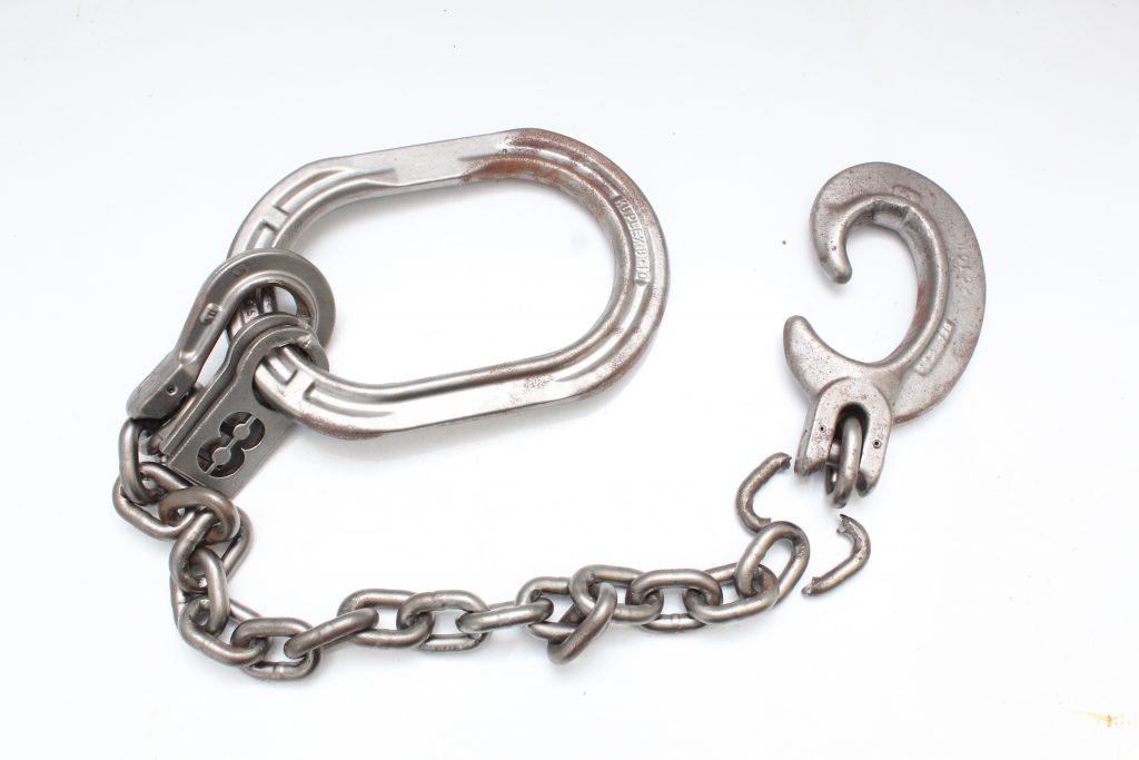
The chain assembly as received.
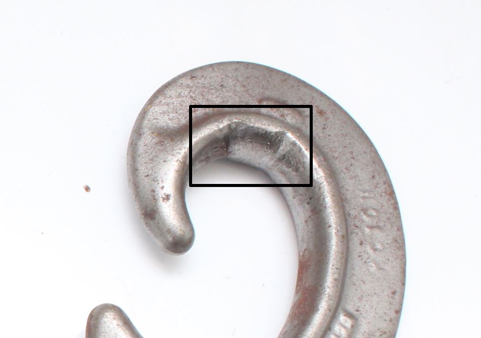
Service wear on the hook working surface.
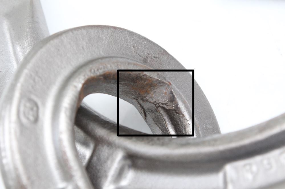
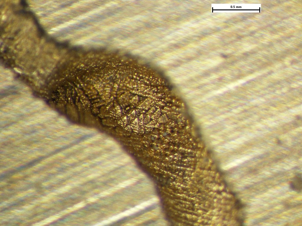
The egg link displaying smeared material consistent with compression against the eye surface.
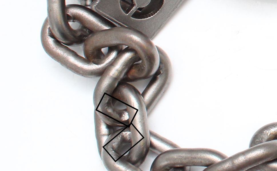
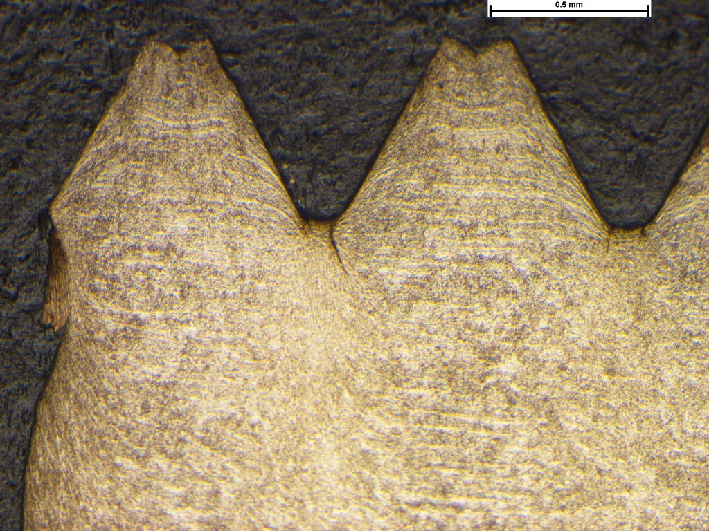
Impressions on the link surfaces.
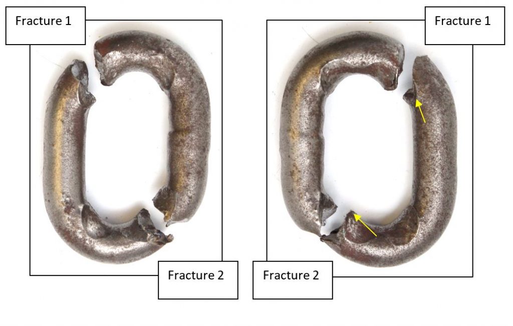
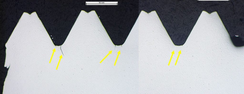
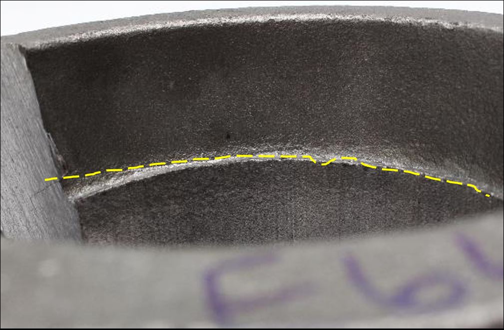
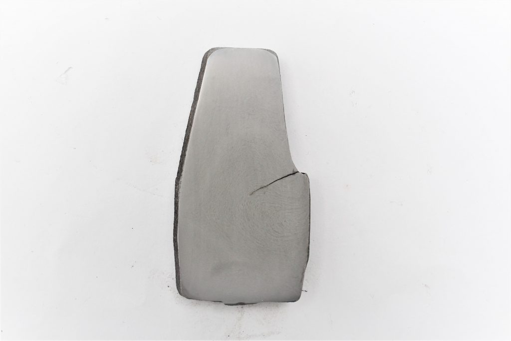
The fractured link sides. Fracture initiation point arrowed.
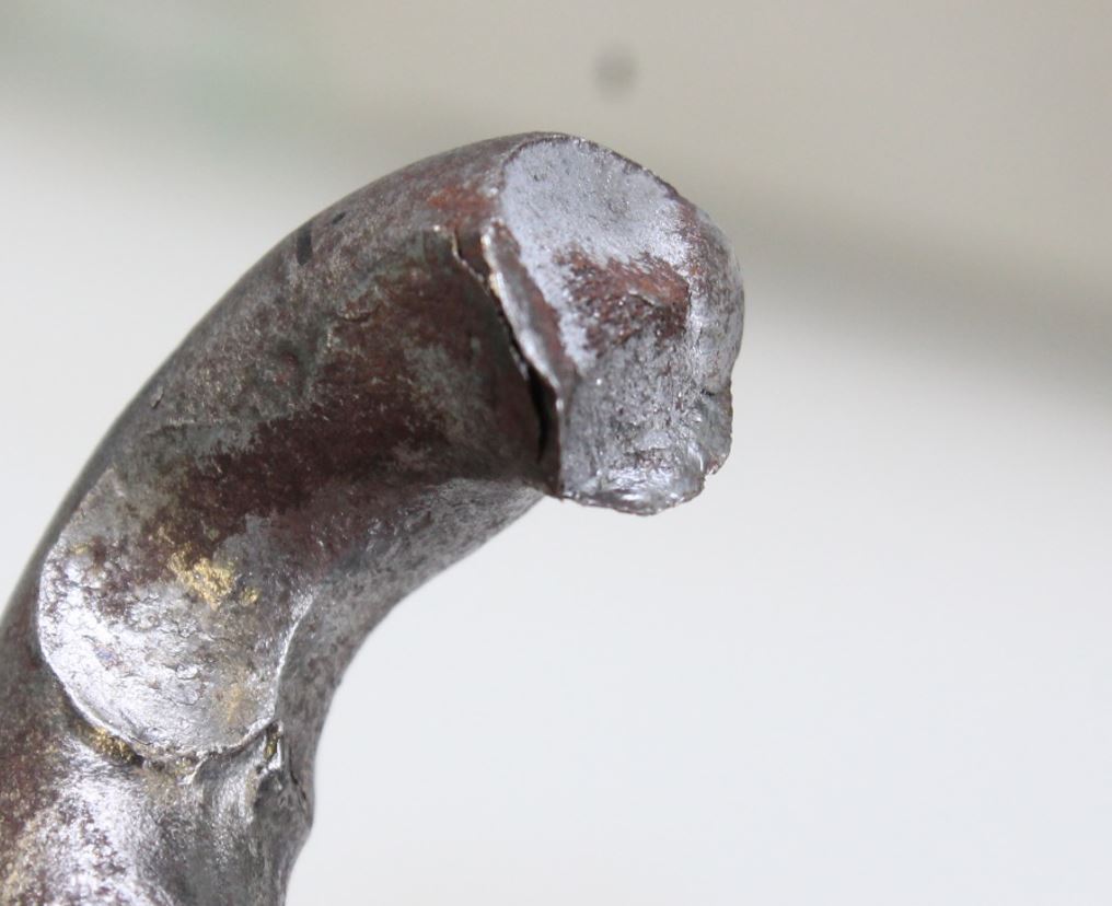
Detail of one of the fractured links showing the deformation and wear of the link.
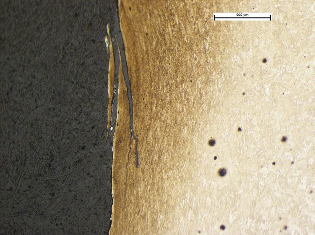
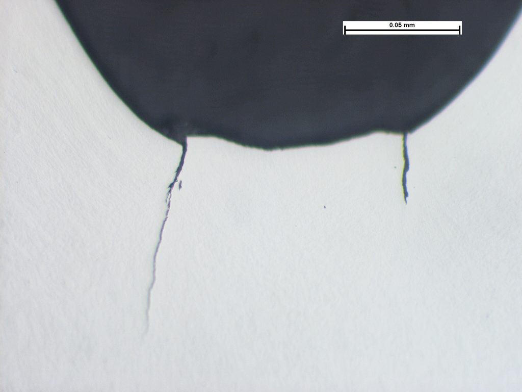
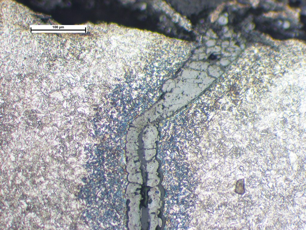
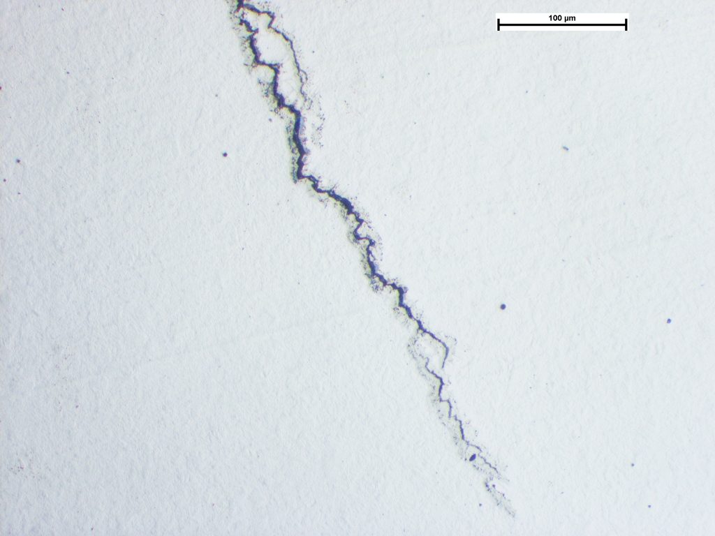
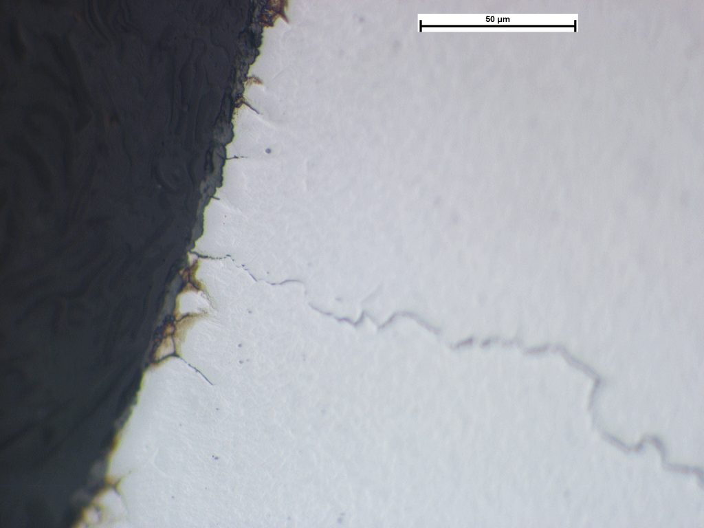
Photomicrograph of section through the smeared surface of a chain link in the vicinity of the fracture initiation. Image taken at x100 magnification.
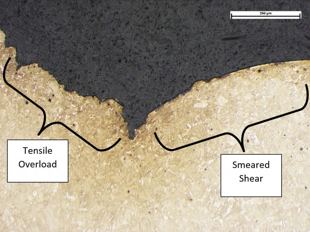
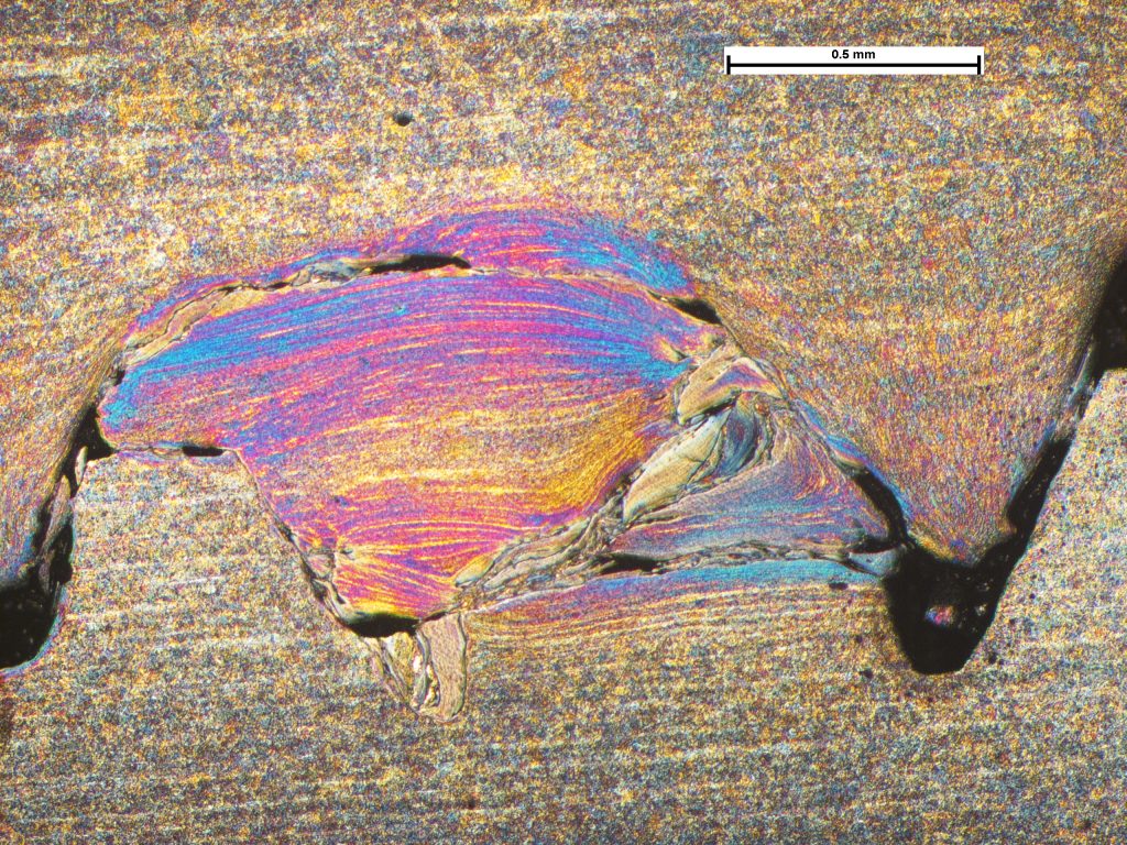
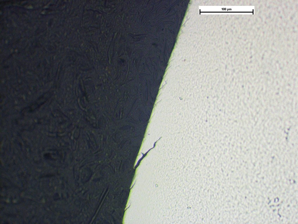
Photomicrograph of a section through the central portion of a fracture displaying a transition between tensile overload (left) and shear overload (right). Image taken at X100.
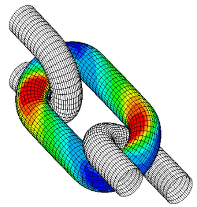
FEA analysis of torsion of a chain assembly.
Torsional Overload of Lifting Chain
Fractured chain used in service to lift a skip used inside a grit-blasting chamber. The chain consisted of 10mm links with a C-hook, an ‘egg link’, and an eye. Examinations revealed the cause of chain fracture to be in-service stresses rather than material or manufacturing defects. General service wear was observed on the hook and significant wear, from the grit blasting, was observed on all of the surfaces. However, this had not significantly reduced the chain link diameters or significantly compromised the chain integrity. Under normal loading for a chain, the contact surfaces would be expected to be at the middle of the U-shaped ends of the links. Significant wear and plastic deformation of the chain was observed on the link surfaces and the egg link at the transition from the curved ends to the straight sides of the links, in a manner that could only be achieved with the chain twisted whilst under load. In addition to the surface wear and deformation, which resulted in a reduction in cross sectional area, reducing the load-carrying capacity, crack-like defects (stress concentrators) were produced. Furthermore, twisting of the chain will also have resulted in increased stresses, at the location of the areas of deformation, as illustrated in the FEA image taken from a published paper. This shows how, when torsion is applied, chain links press against other each and impose a side load that results in a bending stress (shown as red in the image). It seems possible that the chain will have been twisted when loose, prior to the application of load, although this could not be corroborated. It was recommended that the procedures involving the use of the chain assembly are reviewed and possible causes of chain twisting are established. https://www.researchgate.net/publication/267648750_Effects_of_Twist_on_Chain_Strength_and_Fatigue_Performance_Small_Scale_Test_Results
Stress Corrosion Cracking of a Copper Alloy Component
A copper alloy component had cracked in service and the cracks exhibited a degree of ‘yawning’ (opening) indicative of the pre...
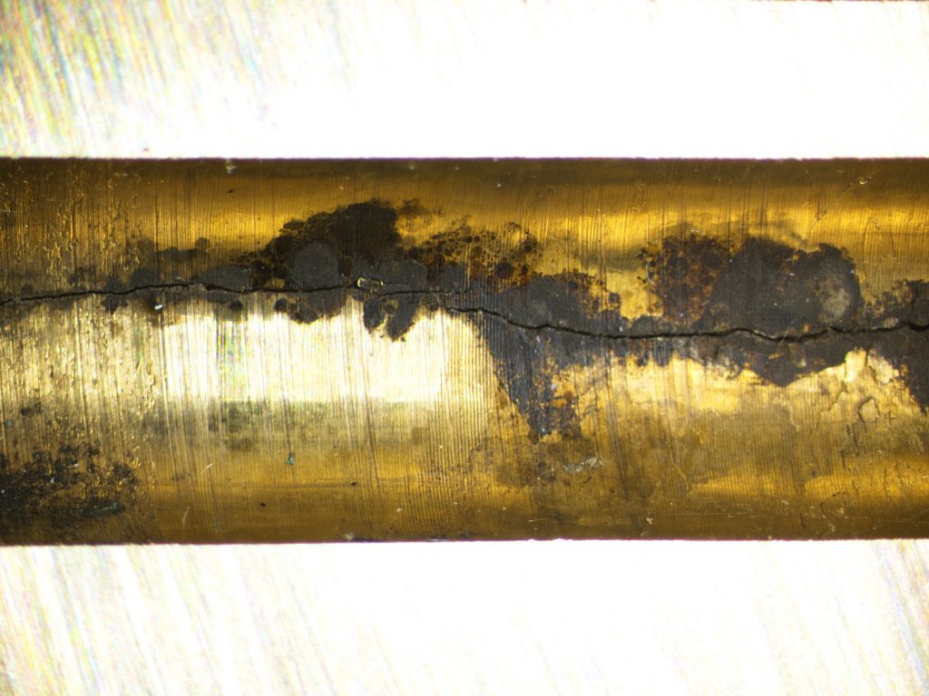
The bore surfaces revealing corrosion product associated with the crack. Noted ‘yawning’ or opening of the crack, indicative of the presence of stress.
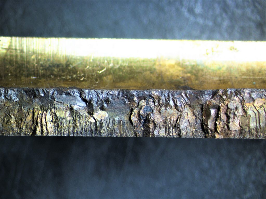
Fracture surface showing general direction of propagation from the bore of the hole (top edge) to the outer surface of the valve body (lower edge). Note coarse brittle fracture surface and heavy corrosion products, consistent with stress-corrosion cracking.
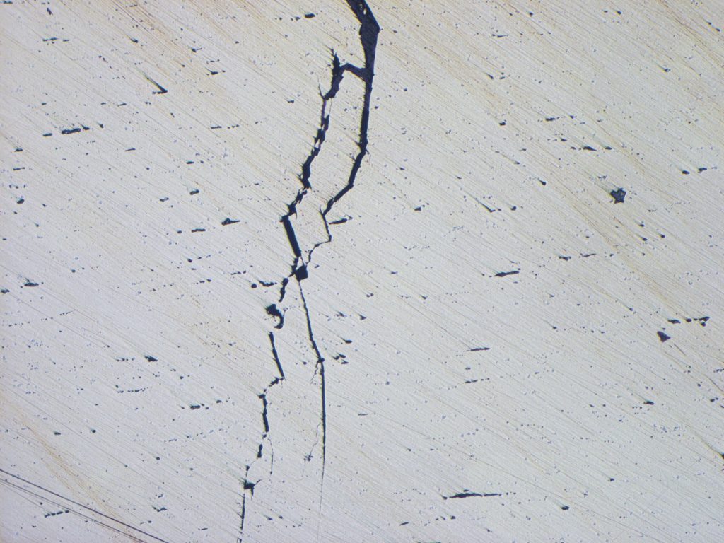
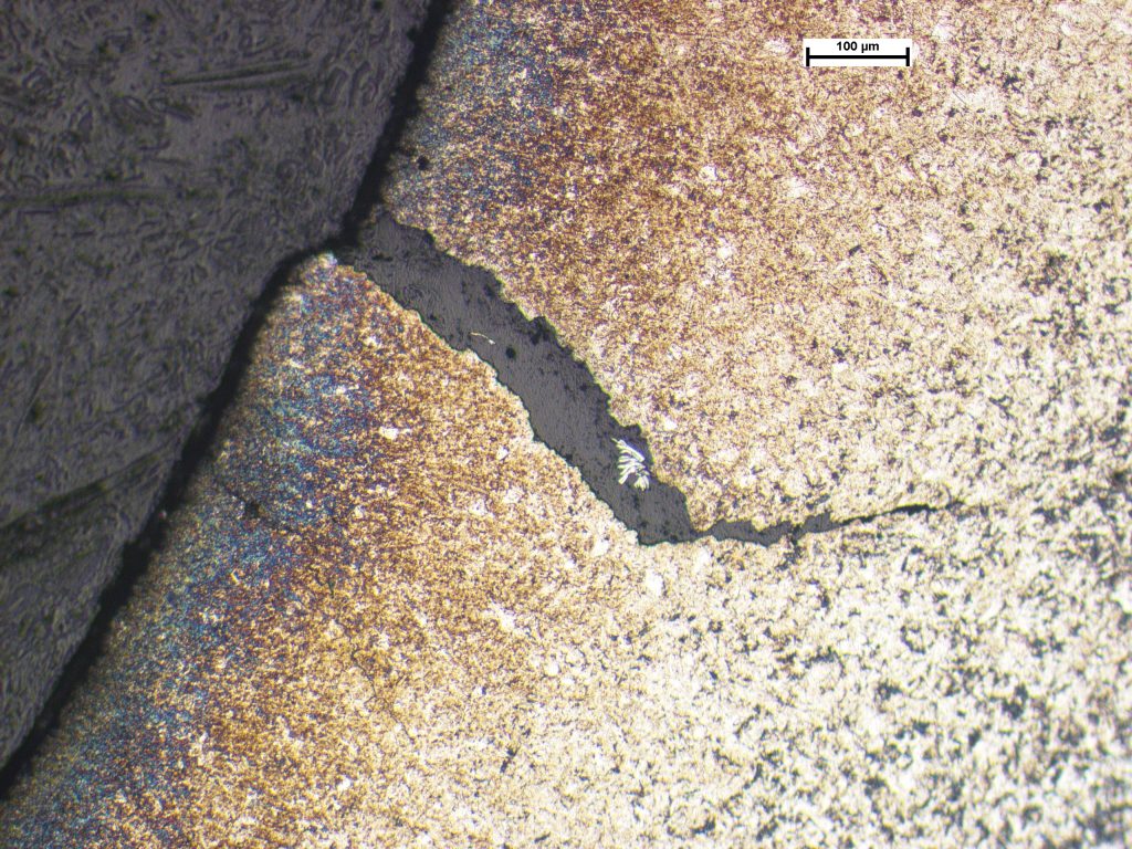
Photomicrograph of section through a representative crack. As polished condition.
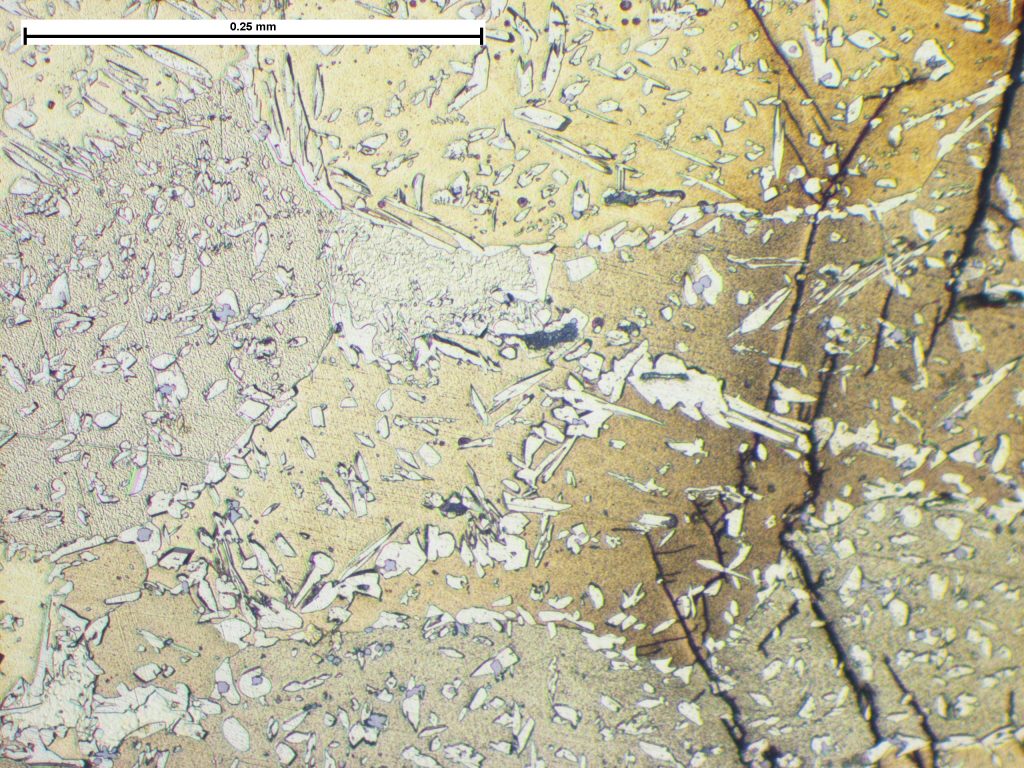
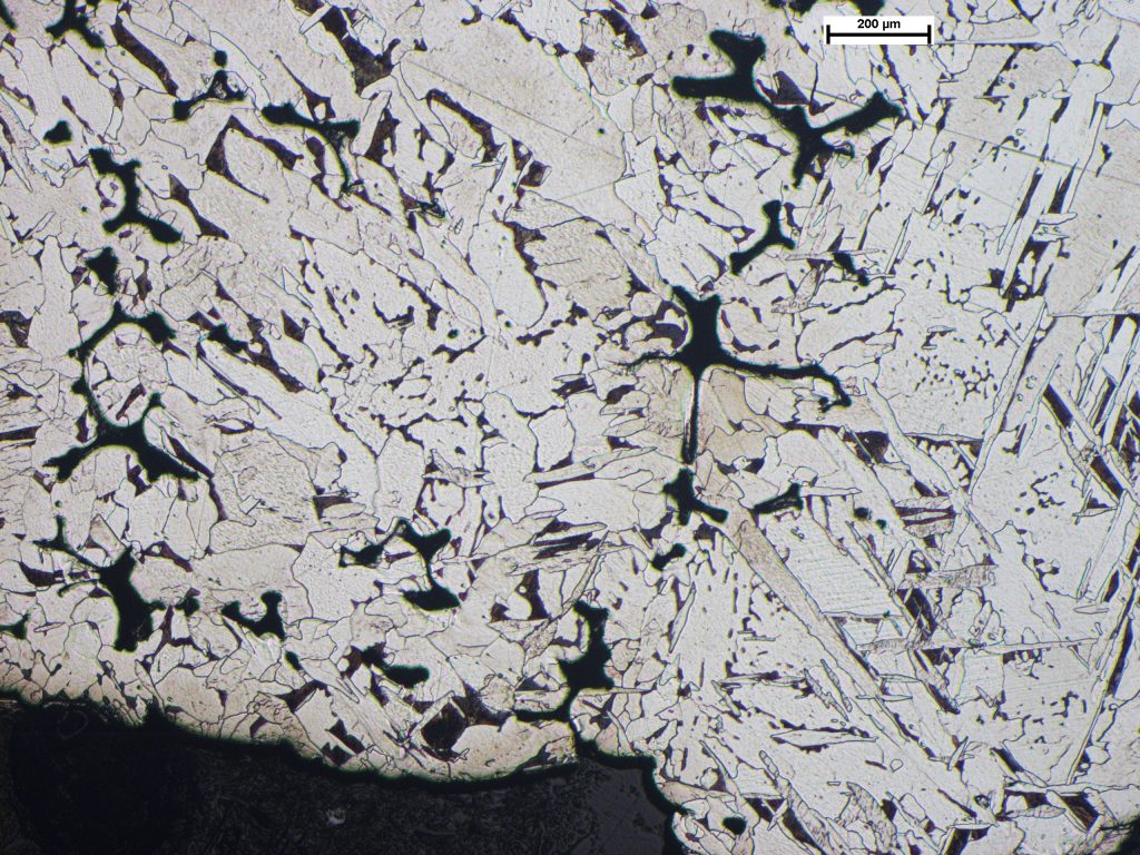
Photomicrograph showing duplex microstructure of alpha and beta phases. Sample etched in acidified ferric chloride. Image taken at x200 magnification.
Stress Corrosion Cracking of a Copper Alloy Component
A copper alloy component had cracked in service and the cracks exhibited a degree of ‘yawning’ (opening) indicative of the presence of tensile stress. This may have been a combination of residual stress from manufacture, and applied (in-service) stress which had effectively pulled the crack surfaces apart. The component was sectioned which revealed corrosion on the bore, either side of the main crack that extended to the outer surface. Exposure of the fracture surfaces revealed a brittle fracture mode with extensive corrosion product. Following metallographic preparation of a microsection through the cracking the microstructure was observed to consist of a duplex structure of alpha and beta phases, consistent with a copper-zinc alloy. The cracks were heavily branched and exhibited extensive corrosion attack, consistent with a stress-corrosion cracking (SCC) mechanism. SCC is a progressive mode of propagation caused by a combination of tensile stress and an environment that is corrosive to the material. SCC in copper alloys can be attributed to amines or ammonia-like compounds.
Casting Defect in Copper Alloy
Tapping Tee joints used in water pipe applications had been found to leak from a pin hole defect after installation in service. Th...
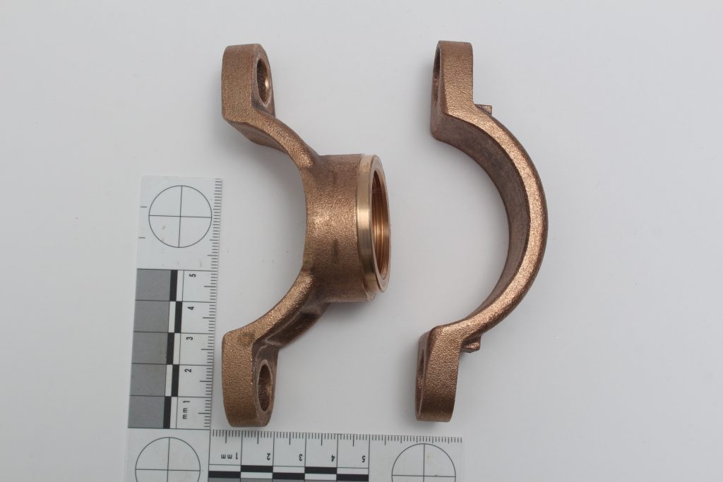
The castings as-received.
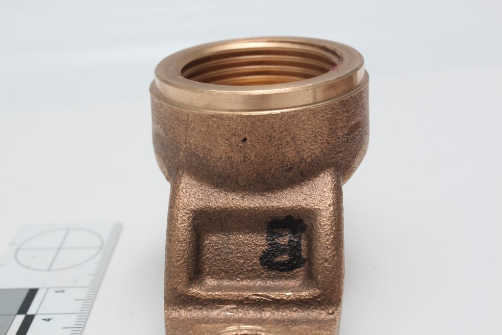
Casting showing location of pin hole.
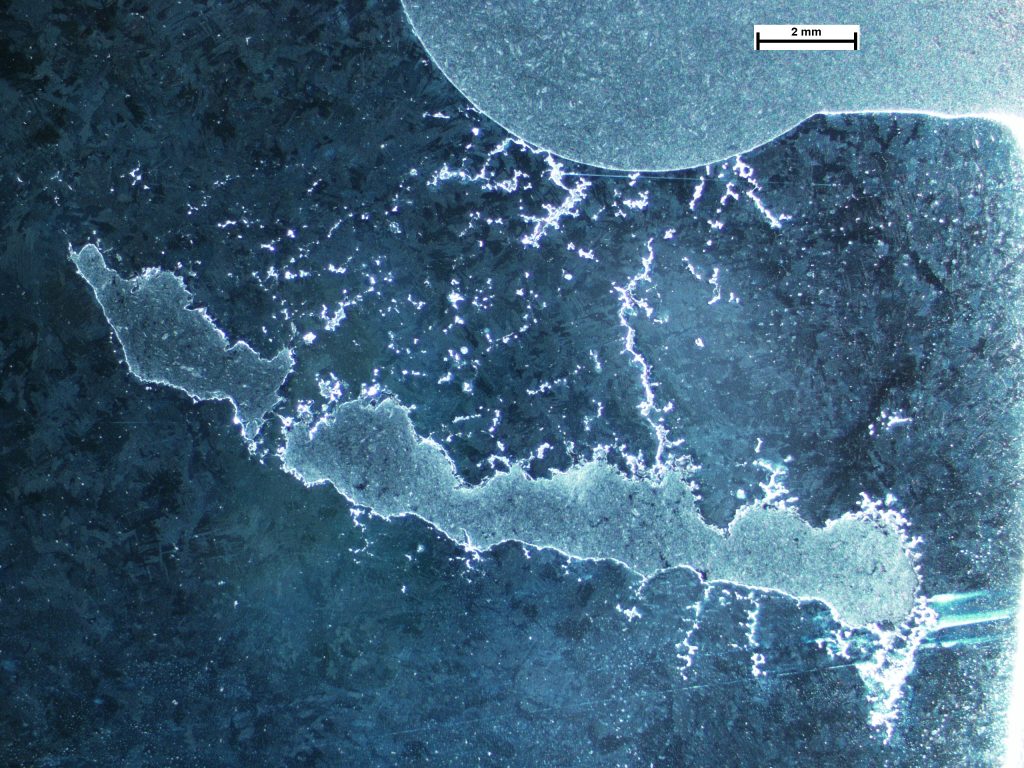
Polished and etched section through the location of the pin hole showing elongated ‘worm hole’ defect and cracking at the O-ring seat recess . Surface etched in acidified ferric chloride to reveal the grain macrostructure.
Detail of the surface of a ‘worm hole’ showing dendritic nature of surface (‘fir trees’), consistent with a casting defect.
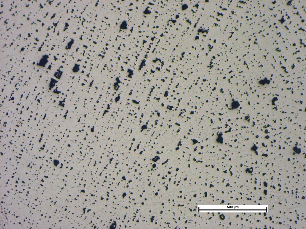
Photomicrograph of section through the casting showing distribution of shrinkage voids. Sample polished. Image taken at X50 Mag.
Casting Defect in Copper Alloy
Tapping Tee joints used in water pipe applications had been found to leak from a pin hole defect after installation in service. The client reported that the leaks typically occurred in the same position on all the affected castings, rather than isolated and random occurrences. A section was taken through a defect which revealed extensive elongated voids and cracks. At higher magnification these were found to exhibit dendrites typical of a casting defect. The microstructure consisted of a cored alpha solid solution, interspersed with lead particles, with extensive shrinkage voids. Examinations suggested an inherent problem with either one or both of, 1) the mould design, or 2) the casting parameters, such that flow characteristics of the molten metal and subsequent cooling and solidification caused the defects to always occur at the same location. It was recommended that the mould design and casting parameters be reviewed by the foundry to prevent recurrence.
Casting Defect in Cast Steel flange
The crack propagation was consistent with the opening (and joining up) of pre-existing interdendritic shrinkage cracks. A shrinkag...
The flange sample as received – pre-sectioned and machined.
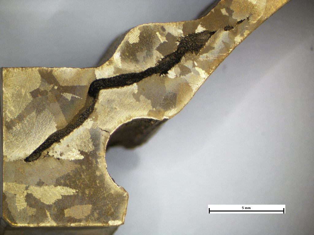
View of the surface and cross section displaying the solidification cavity and dominant crack (arrowed).
Macro image of the polished microsection displaying a network of shrinkage cracks and porosity between the surface and the main shrinkage cavity. Image taken at X6.
Area above the main shrinkage cavity displaying interdendritic shrinkage cracks (arrowed) . Image taken at X50.
Casting Defect in Cast Steel flange
The crack propagation was consistent with the opening (and joining up) of pre-existing interdendritic shrinkage cracks. A shrinkage cavity was present directly below the cracking in the radius. This will have allowed for increased flex of the flange and exacerbated the inherent material weakness, promoting the opening of the crack. The microstructure was observed to be inhomogeneous and consisted of a predominantly acicular and Widmanstätten ferrite with some pearlite grains which was undesirable and, combined with the shrinkage defects, indicated that the casting parameters were less than optimum.
Degradation of Kolsterising Coating and associated damage
One end of a control arm used in a high temperature environment had seized in service. The control arm exhibited an eyelet, into w...
1- Markings on the pin consistent with fretting.
2- A bright area on the surface of the eye of the seized end.
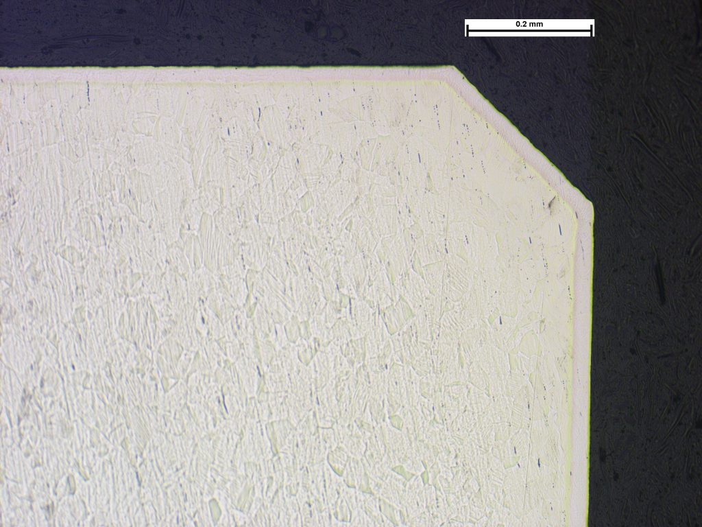
3- Reference sample – Image taken at X100.
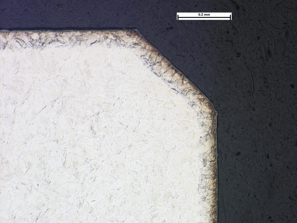
4- Seized end – Chamfer area. Image taken at X100.
Degradation of Kolsterising Coating and associated damage
One end of a control arm used in a high temperature environment had seized in service. The control arm exhibited an eyelet, into which fitted a pin or boss. The pin was manufactured from a martensitic stainless steel and the control arm and eyes were manufactured from 316 austenitic stainless steel. The contact surfaces of the eyelet had been subjected to a surface conversion process called Kolsterising which significantly increases hardness, and resistance to wear and galling. Examination revealed that the surfaces of the seized eye and boss had degraded by a fretting mechanism with the resulting deposits having caused seizure of the joint. Metallurgical examination of sections through the failed eyelets and reference samples indicated that the eyelets on the reference sample and unaffected end of the incident arm exhibited a surface conversion, consistent with having been Kolsterised. However, at the seized end, the coating differed, including in areas where no contact with the pin had occurred. Data from the client indicated that the seized end may have been overheated, to temperatures in the order of 700°C for some hours; a Kolsterised surface should provide stable hardness and resistance to degradation up to approximately 500°C. The change in the observed surface conversion at the seized end was consistent with is degradation at the high temperature, ultimately lading to failure of the surface, fretting, and ultimately seizure.
Fracture of Aluminium Component Due to a Casting Defect
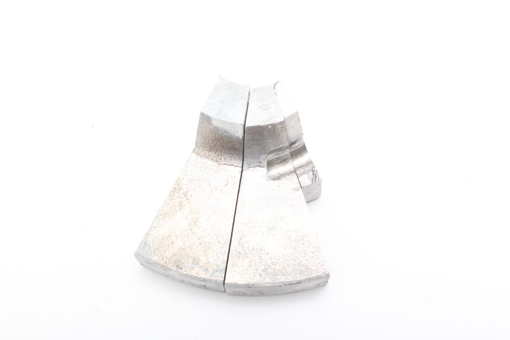
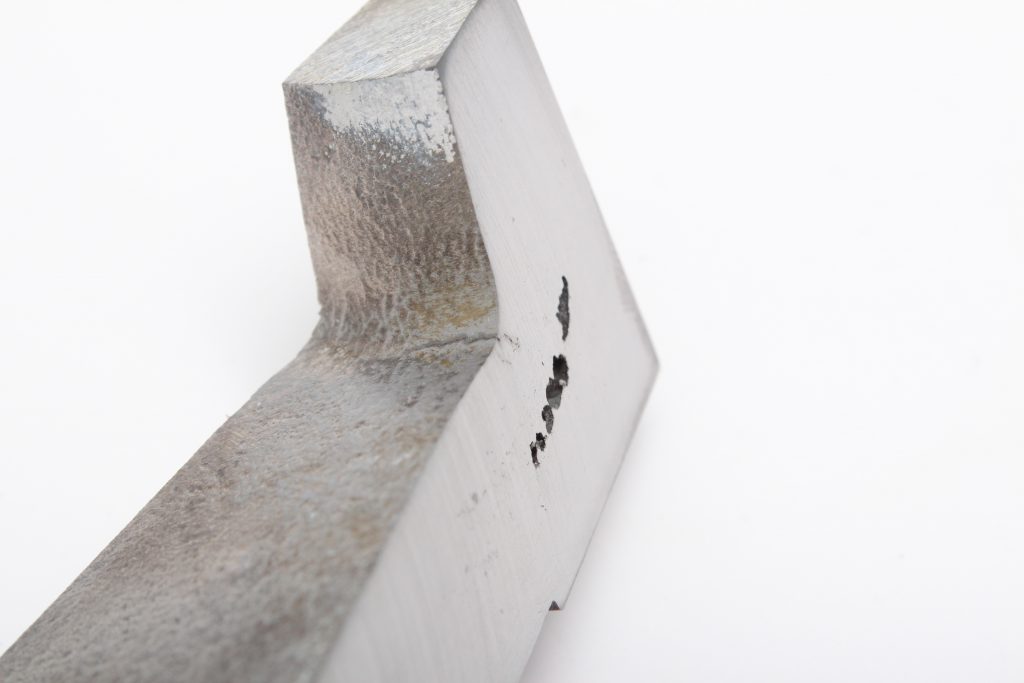
Examination of the fracture at low magnification revealed a change in fracture surface colour and form for approximately two third...
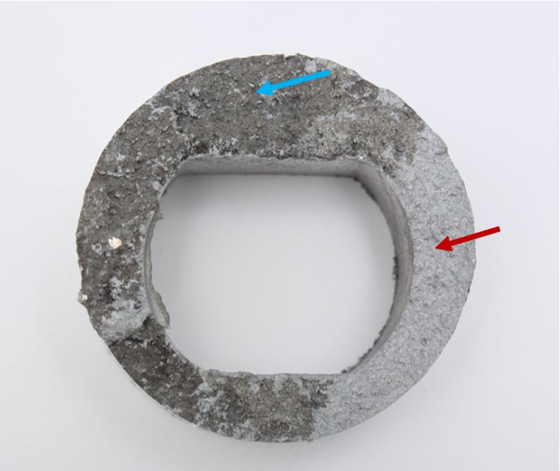
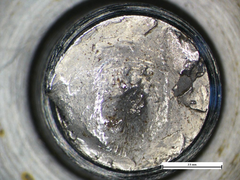
Plan view of the fracture face displaying the ‘dark’ areas (blue arrow) and ‘bright’ areas (red arrow).
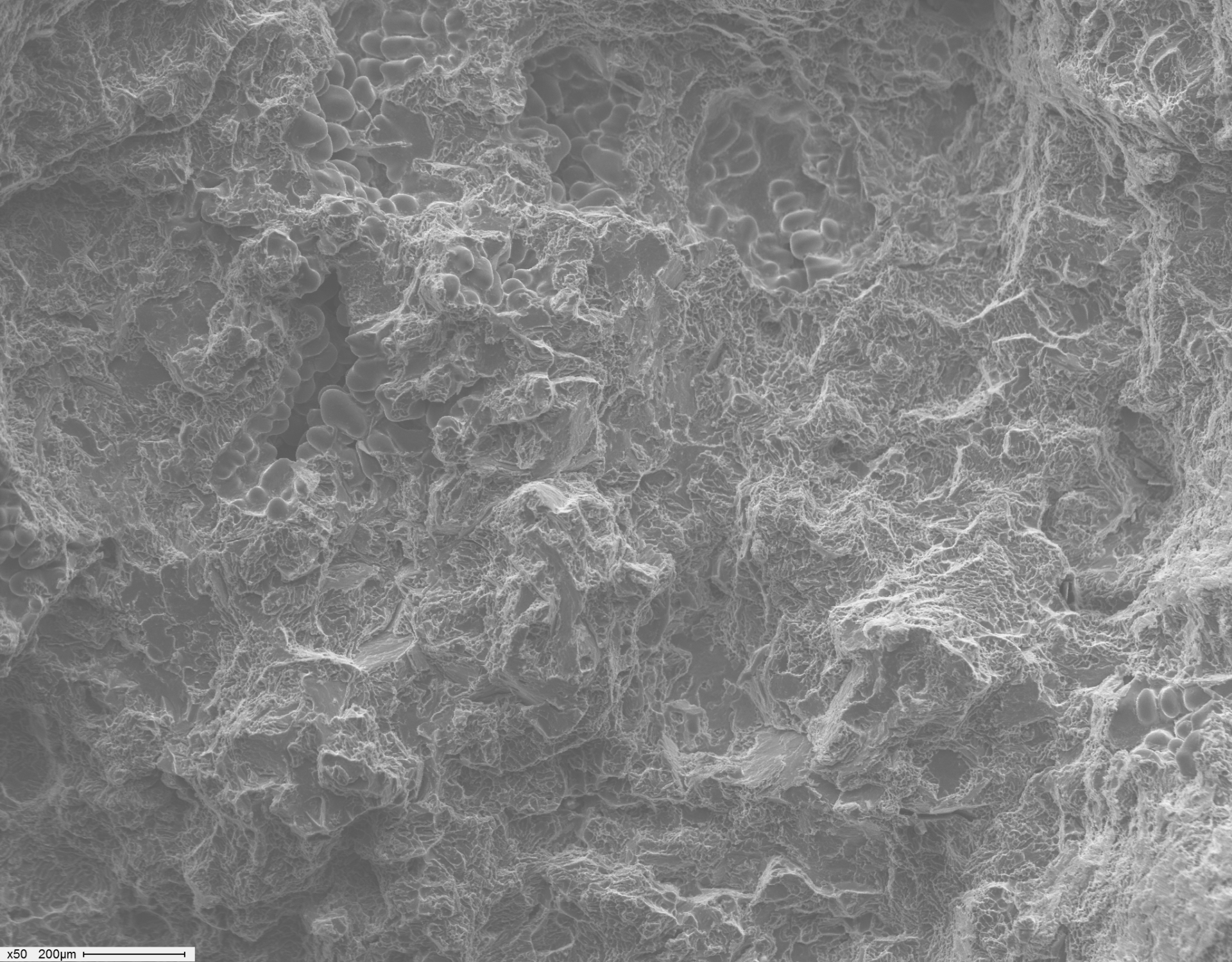
Bright area displaying quasi-cleavage fracture and unfused dendrites. Image taken at X50.
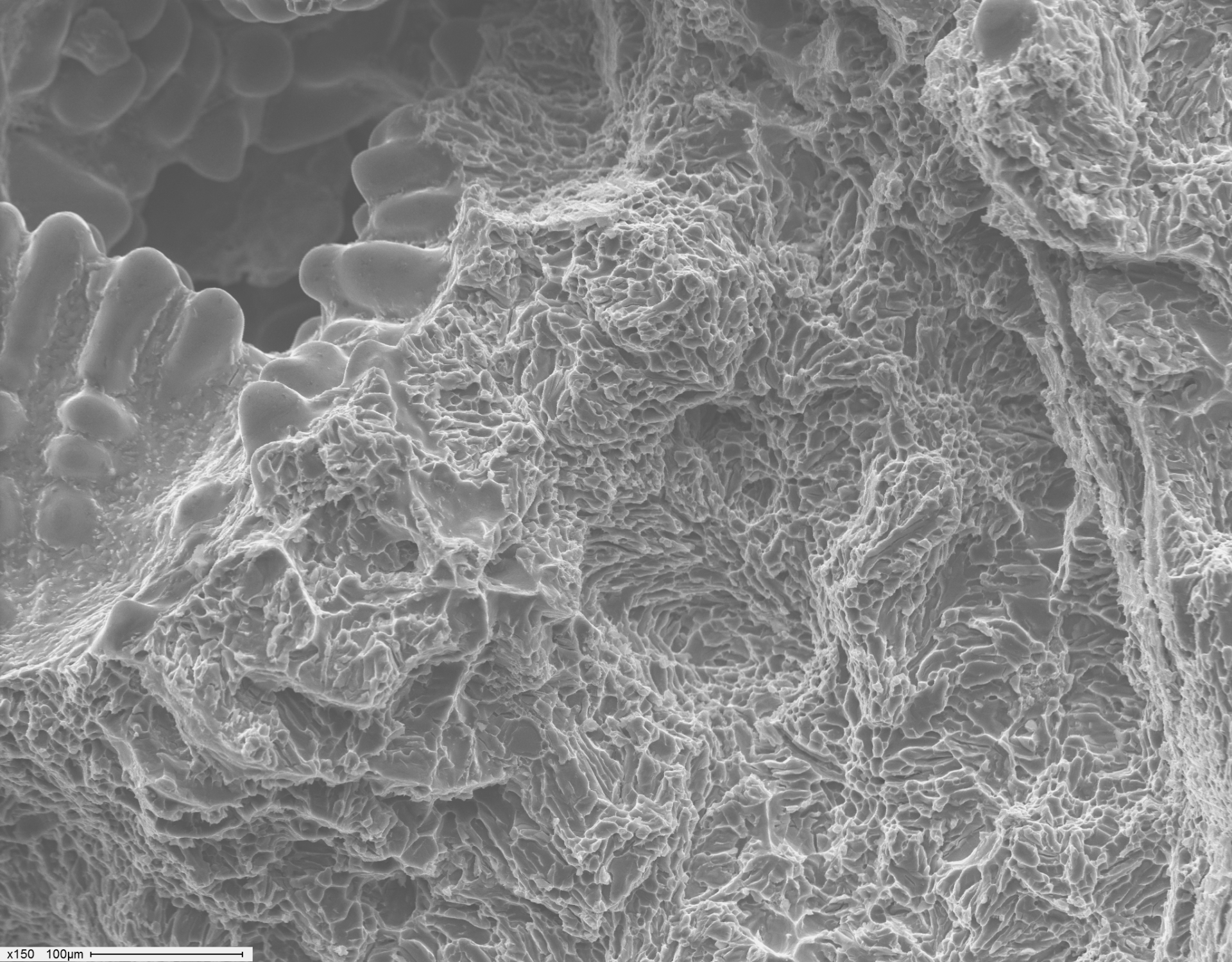
Bright area displaying quasi-cleavage fracture and unfused dendrites. Image taken at X150.
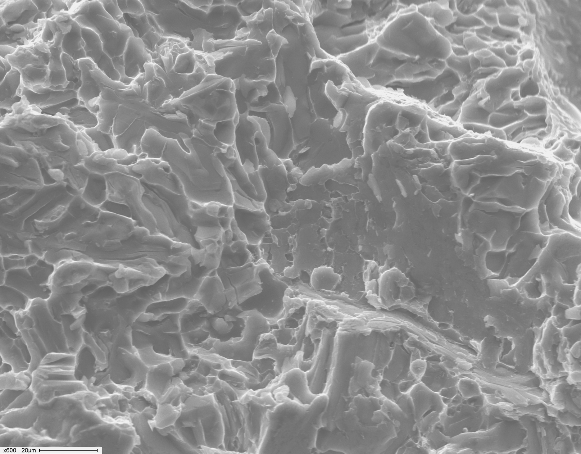
Bright area displaying quasi-cleavage fracture. Image taken at X600.
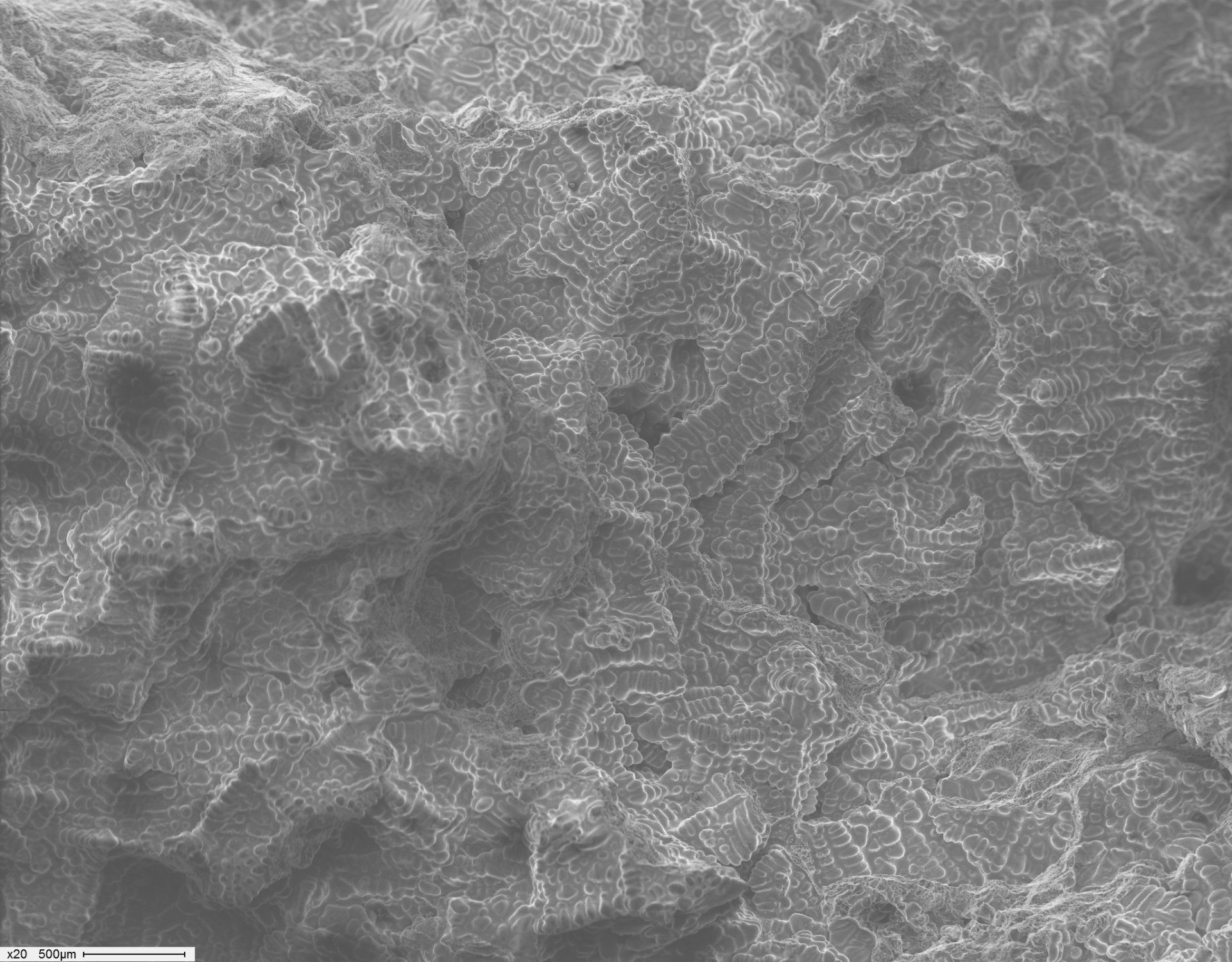
Dark area displaying unfused dendrites. Image taken at X20.
Fracture of Aluminium Component Due to a Casting Defect
Examination of the fracture at low magnification revealed a change in fracture surface colour and form for approximately two thirds of the surface area. Examination at higher magnification using the scanning electron microscope revealed the darker areas of fracture to be consistent with dendrites of unfused material. This is indicative of a casting defect such as shrinkage or cold shut.
Torsional Overload of Threaded Shaft
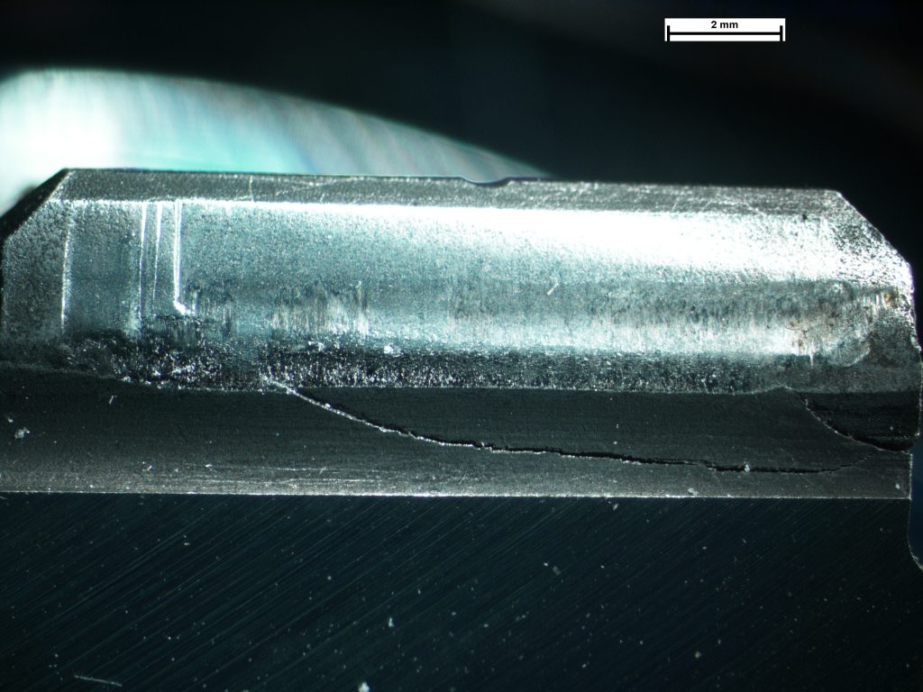
A threaded shaft had fractured at an end face of a nut. The shaft had failed by torsional overload and evidence of twisting of th...
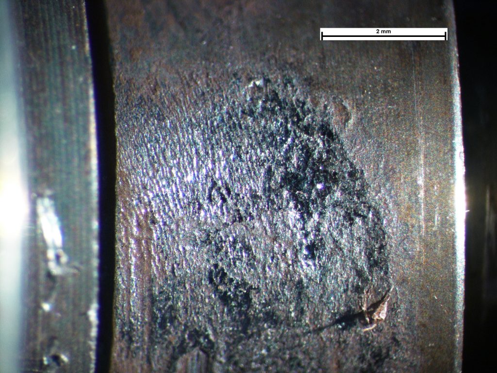
The fracture face displaying markings consistent with torsional overload.
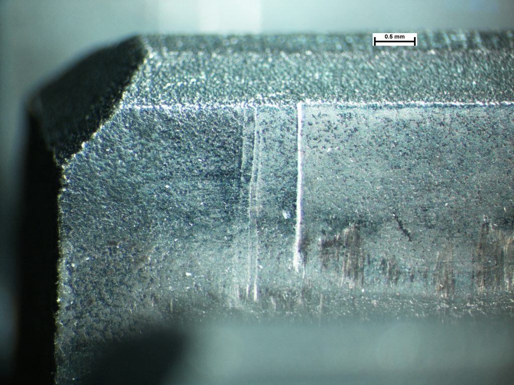
Composite image revealing cracks in the thread roots.
Two circumferential cracks in the thread root adjacent to the fracture, with deformation of the thread form.
The etched shaft threads revealing material deformation extending from the thread roots, caused by twisting (rotational deformation) of the bolt section.
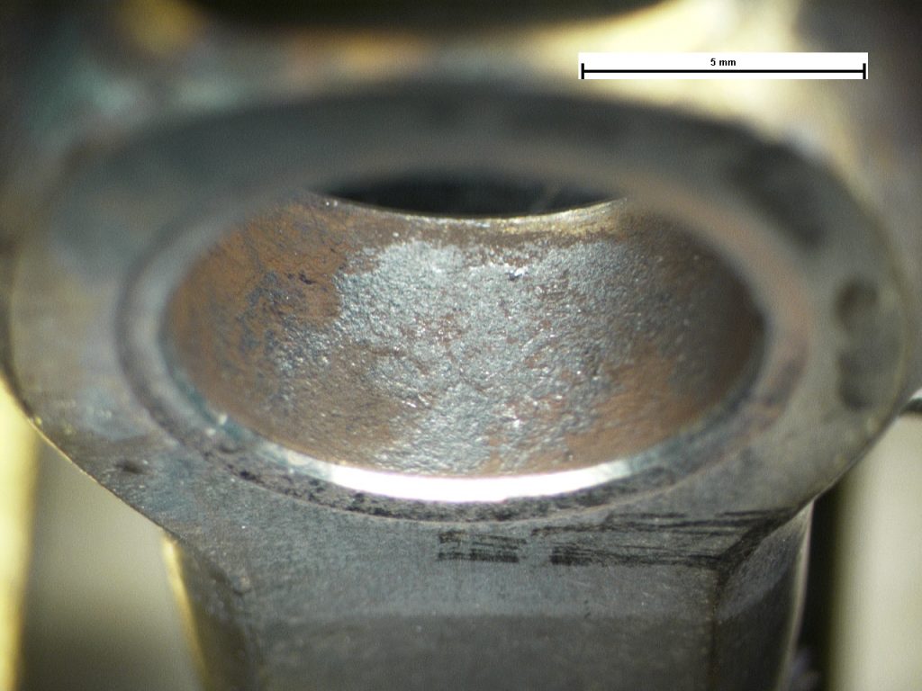
Galling and deformation of the threads at the centre of the shaft/nut interface.
Torsional Overload of Threaded Shaft
A threaded shaft had fractured at an end face of a nut. The shaft had failed by torsional overload and evidence of twisting of the bolt section was observed on microexamination of cross-sections. A longitudinal section through the shaft and which included the nut, revealed extensive galling damage to the threads in the central section of the nut only, whilst no damage was observed on the sections of thread either side of the nut. The form of the damage was consistent with ‘pick-up’ and gross galling of material in the latter stages of installation rather than an effect of being in service. The nut had not been ‘cross-threaded’, nor had generated damage in the early stages of being rotated on the shaft threads. The result of this damage would be to have increased the torsional loading to drive the nut along the shaft threads. A torque loading was not specified for the application and this allowed excessive torque to be applied to the point where the bolt section yielded and then fractured.
Torsional Overload of Crankshaft Spline
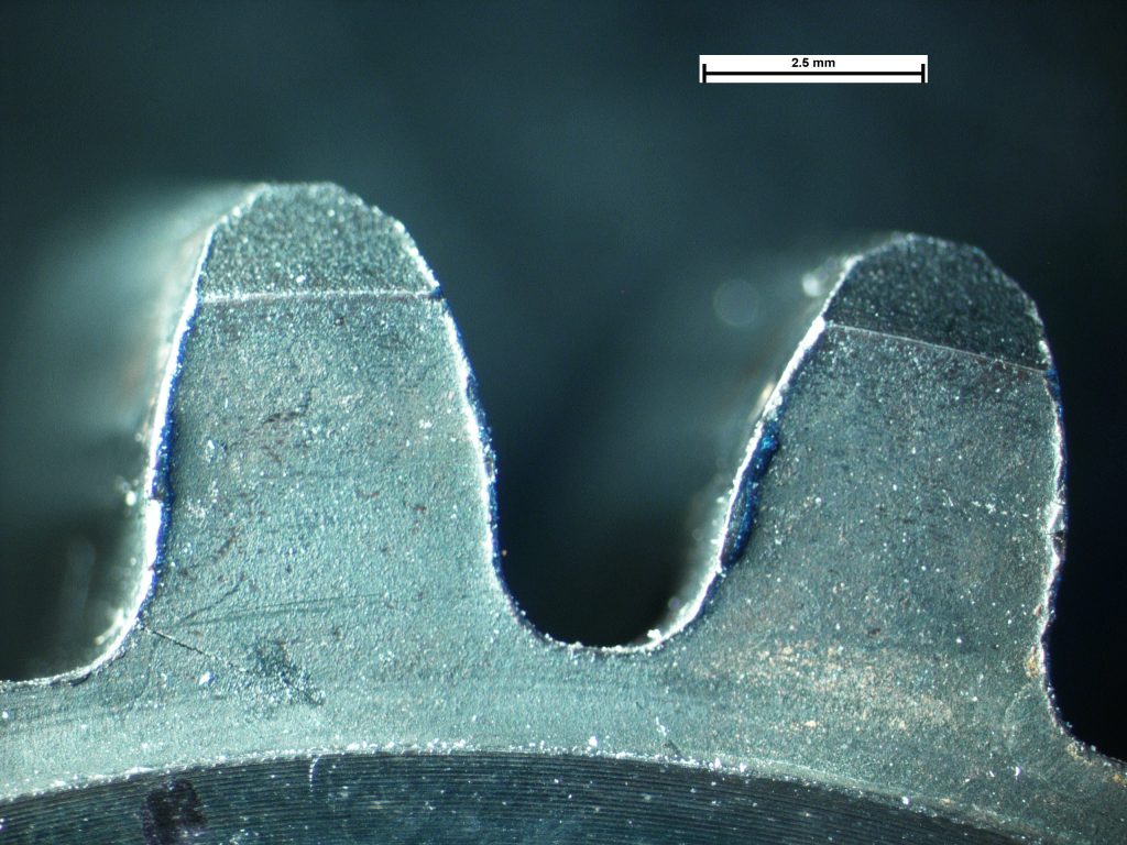
The fracture surface was relatively flat and displayed radial arced markings on the majority of the fracture surface, and a coarse...
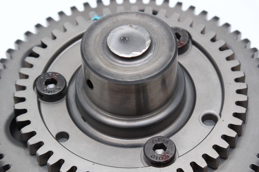
Position of fractured shaft.
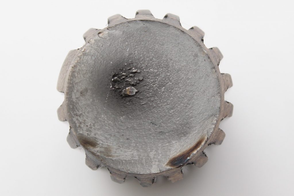
Fracture face.
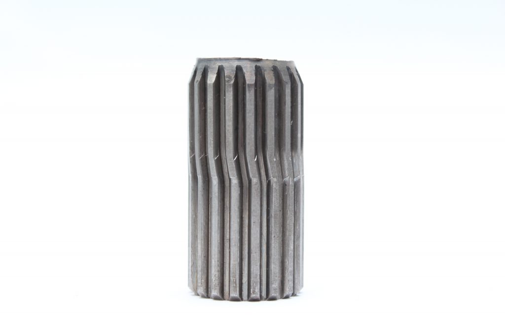
Gross plastic deformation of the shaft due to torsional overload.
Torsional Overload of Crankshaft Spline
The fracture surface was relatively flat and displayed radial arced markings on the majority of the fracture surface, and a coarse area close to the centre, all consistent with torsional overload. Deformation of the splines was observed along with impressions on the spline surfaces which supported the fractographic evidence suggesting a torsional overload event. No defects or evidence of fatigue crack growth were observed on the fracture surfaces.
Staged Overload of Threaded Component
Visual examination of the fracture revealed the initiation portion to be at nominally 45°, which is typical of shear. The fractur...
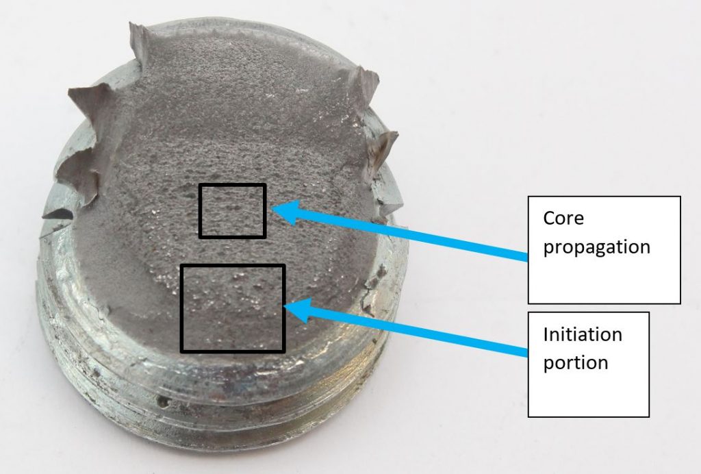
Plan view of the thread portion as received with the areas examined using the SEM highlighted.
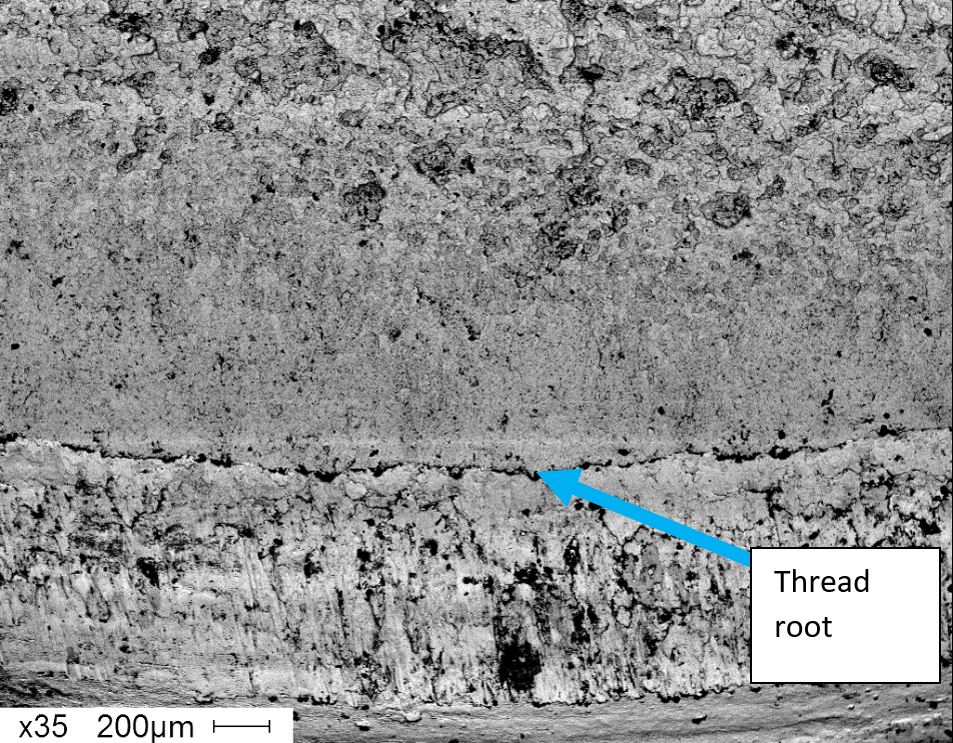
BSE Image of the initiation area. Image taken at X35.
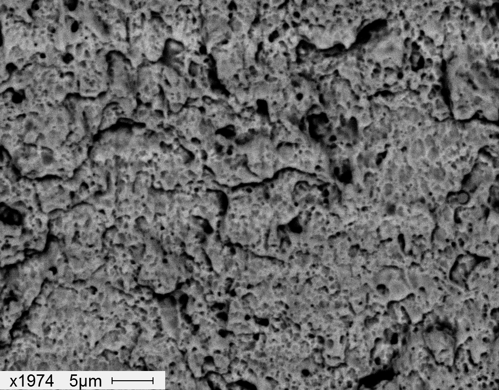
BSE High magnification image of the initiation area. Image taken at X1974
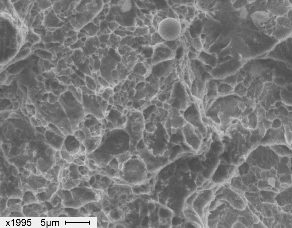
SEI Image of the centre of the fracture. SEI Image taken at X1995.
Staged Overload of Threaded Component
Visual examination of the fracture revealed the initiation portion to be at nominally 45°, which is typical of shear. The fracture through the central portion of the bolt changed orientation to become perpendicular to the bolt axis, indicative of tensile overload. The final section of fracture also occurred at an angle of approximately 45° and again was typical of shear fracture of the remaining ligament of material. The overall form of the fracture was consistent with unidirectional bending. The central section of the fracture was coarse and exhibited linear features that were indicative of a degree of progressive or staged crack growth during the overload event. Examination of the fractures by Scanning Electron Microscopy (SEM) revealed a degree of ductility with deformation and microvoid coalescence.
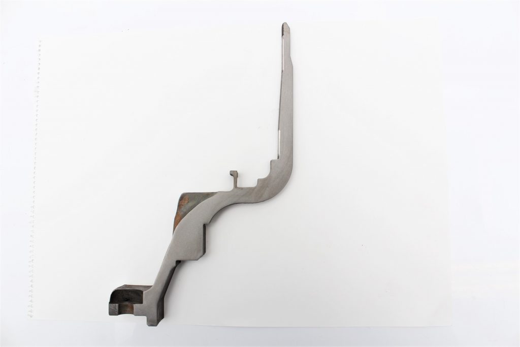
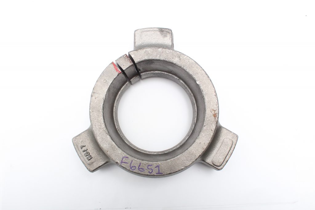
Reverse Engineering of 1960s Locomotive Component
A bell housing used on a 1960’s locomotive required remanufacturing and the original component, that was beyond economical repai...
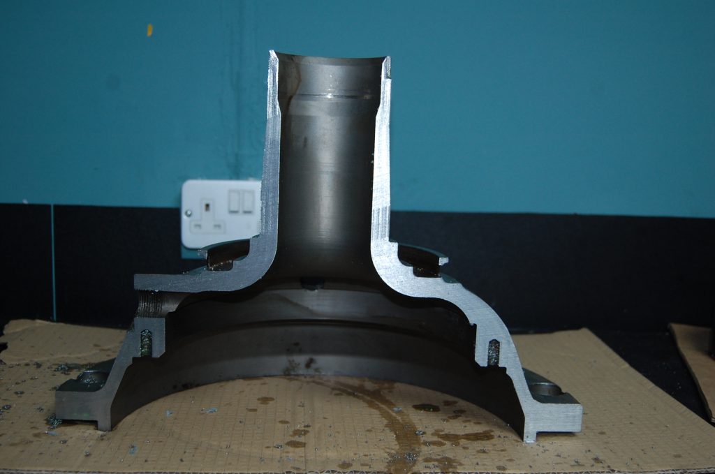
The sectioned housing showing .
A portion of the sidewall displaying forging flow lines and two areas consistent with surface conversion by metal spraying.
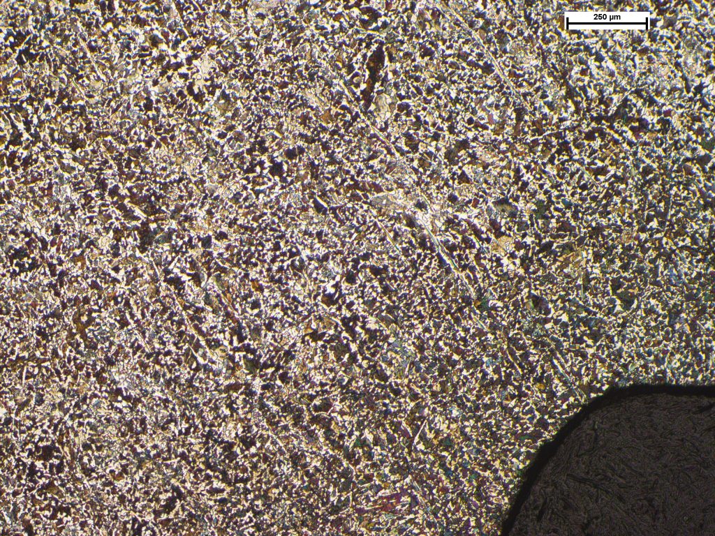
Microstructure of the central ring portion displaying bands of ferrite and pearlite. Image taken at X50.
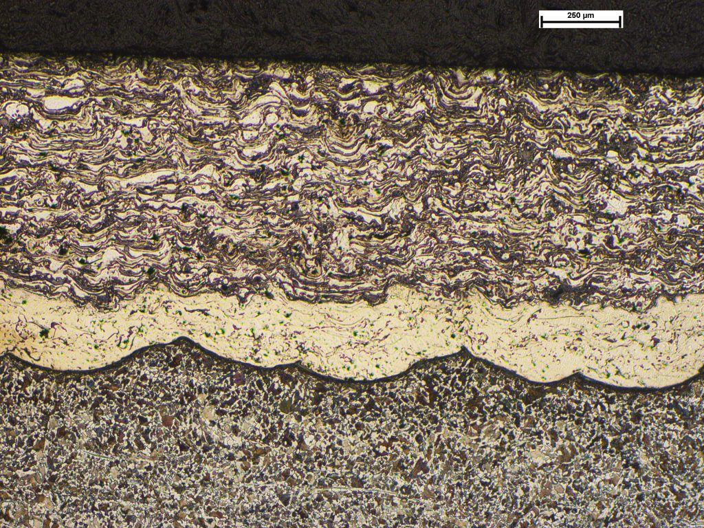
Undulating bands of deposited metal consistent with metal spraying. Image taken at X50.
Reverse Engineering of 1960s Locomotive Component
A bell housing used on a 1960’s locomotive required remanufacturing and the original component, that was beyond economical repair, was subjected to metallurgical examination to assess the materials and manufacturing processes. Examination revealed material flowlines that showed the component had been forged. Two areas exhibited metal spraying which was thought to have been carried out to recover bearing surfaces at some point in its history, as they did not offer any advantages over the base material.
Quench Cracking of Forging
A forging was found to be cracked at inspection by using magnetic particle inspection. Metallurgical examination revealed that th...
Section position through the forging.
Circumferential cracking along the inner diameter step.
Etched macrosection revealing the position of the crack.
Oxidation observed within the crack. Image taken at X200.
Crack tip revealing brittle propagation. Image taken at X200.
Quench Cracking of Forging
A forging was found to be cracked at inspection by using magnetic particle inspection. Metallurgical examination revealed that the crack was filled with oxide, consistent with exposure to a high temperature environment, although no indications of decarburisation was observed. The crack had propagated through the material in a brittle manner, consistent with mechanical overload, and had not followed the direction of grain flow i.e. it had occurred after the main forging process had taken place. The presence of thick oxides in the crack, but without decarburisation, indicated that the crack had formed or was present in an oxidising environment at temperatures up to approximately 650°C. From the available information, this was established to be at the end of forging during quenching, or subsequent heat treatment. The crack had initiated at a small change in section, that could have acted as a point of stress concentration, although it was not considered to be significant, such that its contribution to the cracking was probably negligible.
Overload Cracking of Gear
The gear flanks exhibited large amounts of deformation and wear consistent with high loads during service. Cross-sectional examina...
Cracking in the root radius and flank.
Impressions on the gear flank from high contact force.
Cracking in the fillet radius (arrowed) with lips of deformed material at the edges of the teeth.
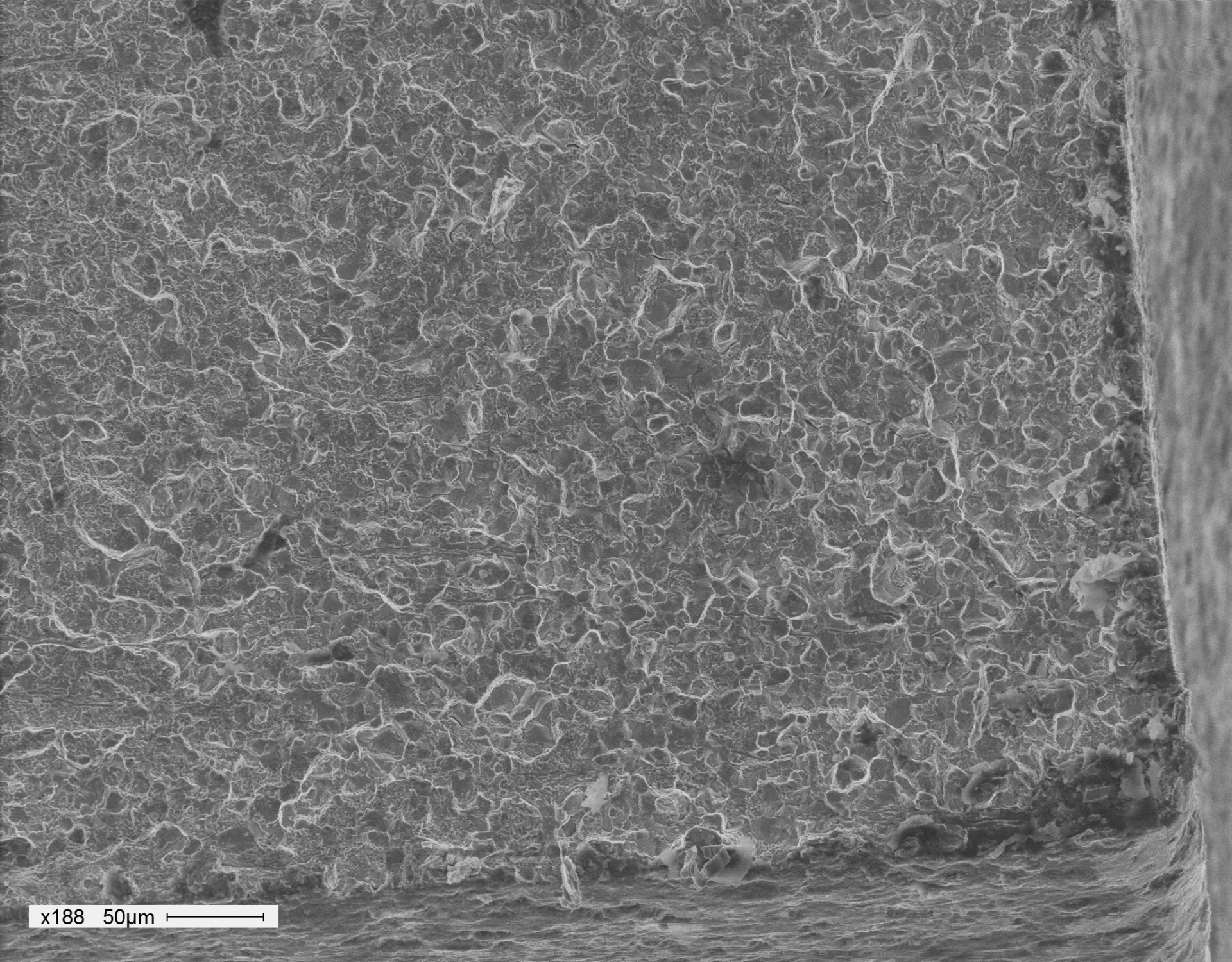
The opened cracked viewed in the SEM displaying trans- and intergranular crack propagation. Image taken at X188.
Intergranular oxidation in the vicinity of the crack start point. Image taken at X500.
Shallow angle cracks at the deformed lower flank surface. Image taken at X200.
Opened crack within the case-hardened portion of the cross section. Image taken at X100.
Overload Cracking of Gear
The gear flanks exhibited large amounts of deformation and wear consistent with high loads during service. Cross-sectional examination of the teeth showed multiple brittle or staged cracks to have propagated from the flank surface though the edge of the case, with dominant cracks opening up in the latter stages of the failure. Intergranular oxidation was observed to the depth of nominally one grain at the surfaces, which was consistent with an artefact of the heat treatment process. These features will have produced a stress concentration and may have contributed to crack initiation.